Hey Guys, Previously we learned How to add text in AutoCAD. Today we are learning about AutoCAD Dimension and Here you will learn about linear dimensions and Dimension lines. Diameter Symbol AutoCAD and Architectural Dimensions
Now, we will learn how to Dimension command from the ‘Annotation’ panel. So, let’s get started.
Know About AutoCAD Dimension
1. The purpose of using the Dimension command is to measure anything that you want according to the unit.
2. By using the dimension command, we can get linear dimension (Line length), Align dimension (slop line length), Angular dimension (Angle between connected two lines), length of the arc, Radius of the circle, Diameter of the circle, Dimension from the (0,0) ordinate, Jogged dimension, etc.
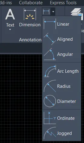
3. We can select the Dimension command from the ‘Annotation’ panel in the Home tab.
4. Or we can use shortcut keys to measure all 8 types of dimensions.
Now we will learn about all types of dimensions.
1. Linear AutoCAD dimension
2. Align AutoCAD dimension
3. Angular AutoCAD Dimension
4. Arc Length
5. Radius
6. Diameter
7. Ordinate
8. Jogged
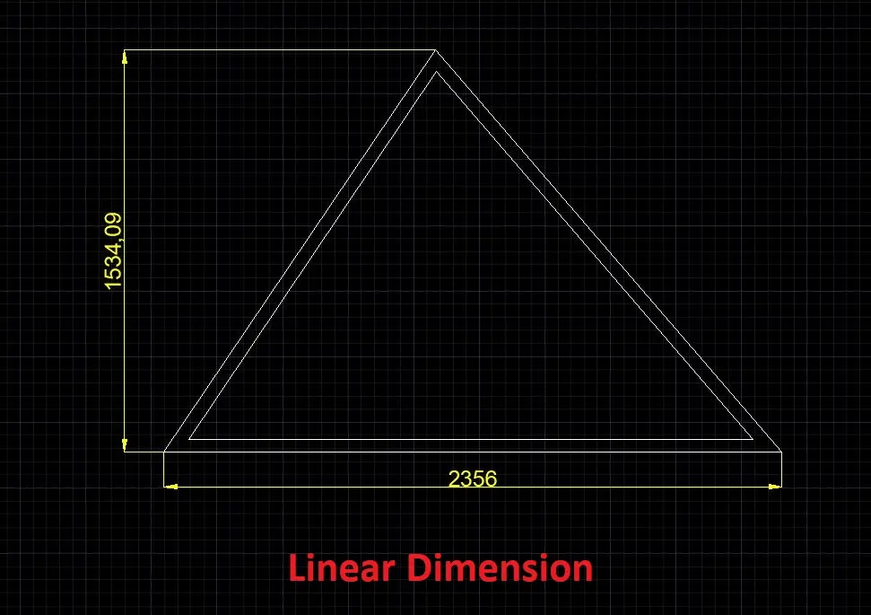
1. Linear AutoCAD dimension
The Linear dimension is created linear dimensions for all types of lines.
Linear dimension means straight dimension, if you measure the sloped line, it will measure only the straight dimension from the first point to the last point.
Select ‘Linear dimension’ from the Annotation panel in the Home tab.
Or type ‘DLI’ in the command bar and press the Enter key.
It will ask for ‘specify first extension line origin’.
Select the first point of line or point of the object that we want to measure.
Then it will ask for ‘specify second extension line object’.
Select the second point of the line or point of the object.
It will ask for ‘specify dimension line location’.
Select the location for the dimension line or we can also give dimensions like 10mm.
It will show as shown.
2. Align AutoCAD Dimension
An Align dimension is created to align the dimensions of lines.
Align dimension means we can measure the proper dimension of the sloped lines.

Select ‘Align dimension’ from the Annotation panel in the Home tab.
Or type ‘DAL’ in the command bar and press the Enter key.
It will ask for ‘specify first extension line origin’.
Select the first point of line or point of the object that we want to measure.
Then it will ask for ‘specify second extension line object’.
Select the second point of the line or point of the object.
It will ask for an ‘extension’.
Select the location for the dimension line or we can also give dimensions like 10mm.
It will show as shown below.
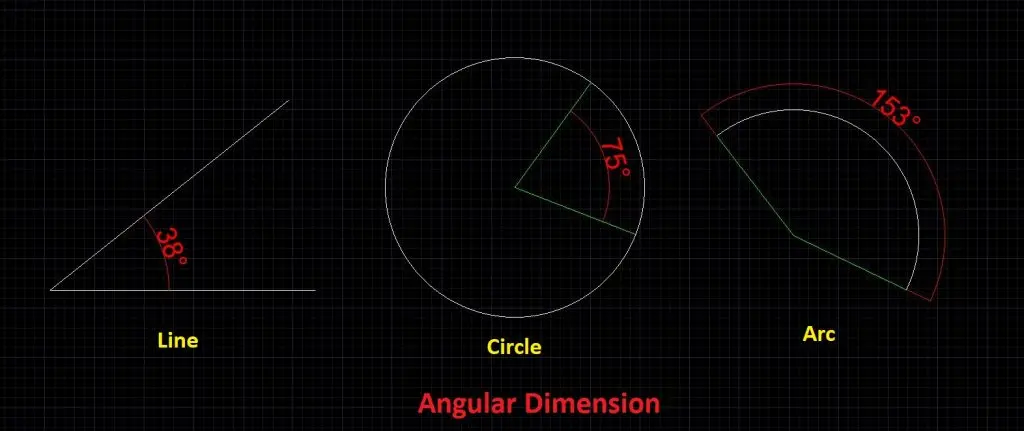
3. Angular AutoCAD Dimension
Angular dimension measures the angle between two lines whether both are joint or not.
It also measures the angle of the arc or angle between two points of the circle.
Select ‘Angular dimension’ from the Annotation panel in the Home tab.
Or type ‘DIMA’ in the command bar and press the Enter key.
It will ask for ‘select arc, circle, and the line’.
Select the first line if we want an angle between two lines select an arc, or select the first point of the circle if we want an angle in a circle.
For arc, selecting arc will show the angle after selecting arc.
For lines, it will ask for ‘select the second line. Select the second line to measure the angle between the two lines.
For a circle, it will ask for ‘select second angle endpoint’.
Select the second point on the circle to measure the angle between the two points.
After selecting the second line for the line or selecting the second point for the circle, it will ask for specifying dimension line location or extension.
Give a particular length or select any location for the dimension line as per requirement.
It will show you a degree symbol as shown.
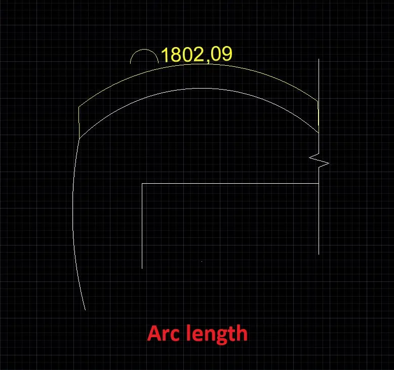
4. Arc Length
The Arc length measures the length of the arc or length of the segment of any polyline.
Select an arc length from the Annotation panel in the Home tab.
Or type ‘DAR’ in the command bar and press the Enter key. ‘AR’ stands for Arc in ‘DAR’.
It will ask for ‘select arc or polyline arc segment’. Select an arc that we want to measure.
Then it will ask for ‘specify arc length dimension location’.
Give the location for arc length as the same as other dimensions.
It will show you an arc-length symbol as shown.
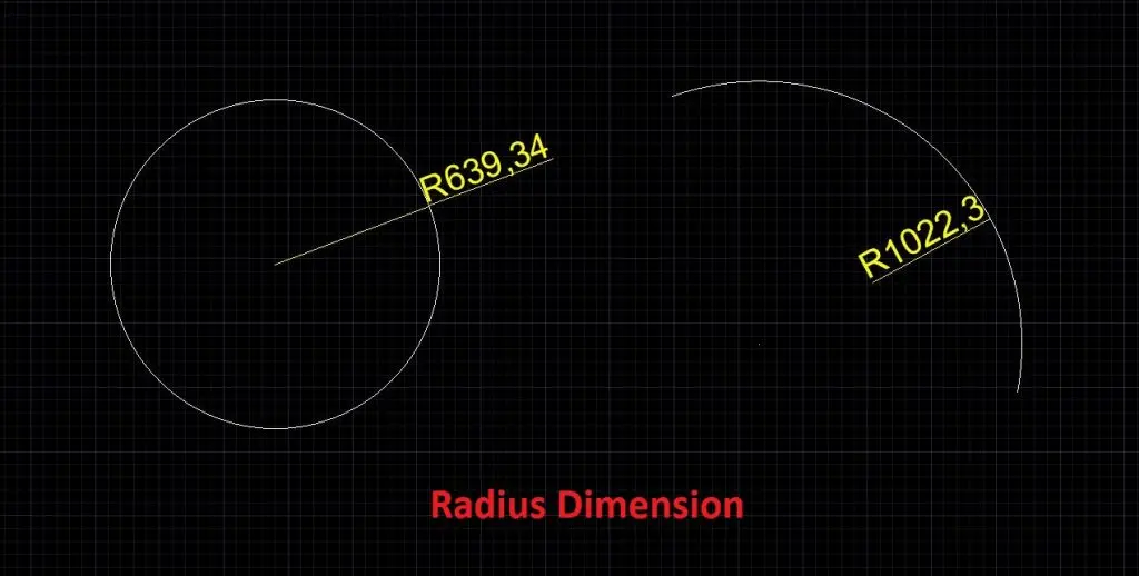
5. Radius
The Radius measures the radius of the circle and arc.
‘Radius means the length of the line from the center of the circle to the outer boundary of the circle.’
Select ‘Radius’ from the Annotation panel in the Home tab.
Or type ‘DRA’ in the command bar and press the Enter key. ‘RA’ stands for Radius in ‘DRA’.
Then the procedure is the same, it will ask for ‘select arc or circle.
After that, it will ask for ‘specify dimension line location’. Give location for dimension line.
It will show the radius with the ‘R’ as shown.
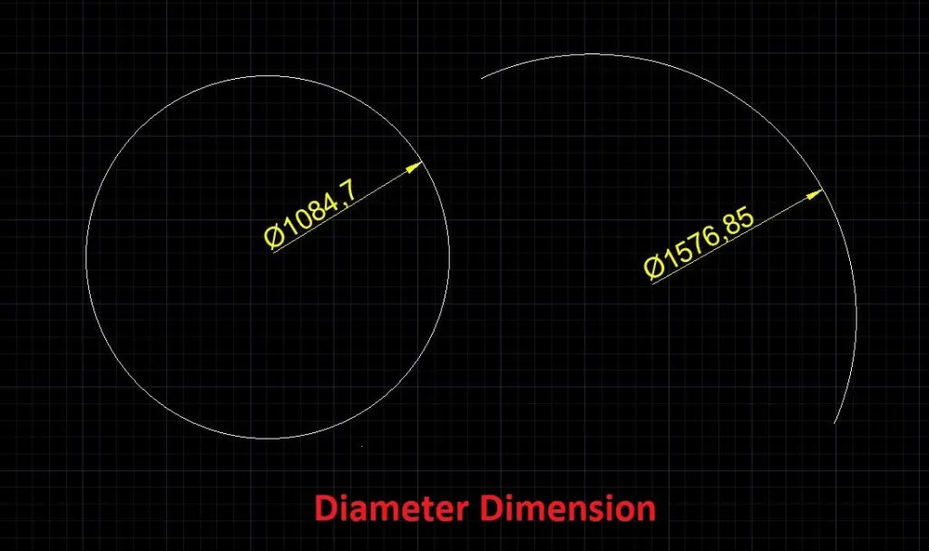
6. Diameter
The diameter measures the diameter of any circle or arc.
Diameter means the length of the straight line which passes through the center of the circle and touches the outer boundary of the circle.’
Select ‘Diameter’ from the Annotation panel in the Home tab.
Or type ‘DDI’ in the command bar and press the Enter key.
‘DI’ stands for diameter in ‘DDI’.
The procedure is the same as the Radius.
Select a circle and then give a location for the dimension line.
It will show the diameter of the circle or arc with the symbol as shown.
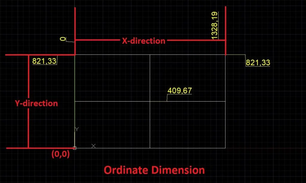
7. Ordinate
The ordinate dimension measures horizontal and vertical length from the (0,0) origin ordinates in the x-direction and y-direction.
This type of dimension is mostly used in the center-line plan or line plan for showing beam and column positions.
Select ‘Ordinate’ from the Annotation panel in the Home tab.
Or type ‘DIMORD’ in the command bar and press the Enter key.
‘ORD’ stands for ordinate in ‘DIMORD’.
It will ask for ‘specify feature location’.
Select the point at which we want the ordinate dimension.
Then it will ask for ‘specify leader endpoint’.
If want ordinates with x-direction, then select a point in the vertical direction.
And if we want to ordinate with a y-direction, select a point in the horizontal direction.
It will show horizontal or vertical length from the (0,0) ordinates.
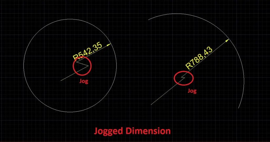
8. Jogged
Jogged dimension measures the Radius of the arc or circle.
But the difference between the Radius dimension and the Jogged dimension is, in the Jogged dimension.
You can set the dimension text location as per your requirement by yourself.
And the dimension line will show in a Jogged shape.
Select ‘Jogged’ from the Annotation panel in the Home tab.
Or type ‘JOG’ in the command bar and press the Enter key.
It will ask for ‘select arc or circle.
Then it will ask for ‘specify center location override’.
Select the point from where you want to show the dimension.
It is not necessary to choose the center point only.
After that, it will ask for ‘specify dimension line location’.
Specify dimension line location as per requirement.
At last, it will ask for ‘specify jog location’.
Specify the jog location where you want.
(NOTE: If you have selected the original center point of the circle or arc, it will not show jog, it will show only the radius of the arc or circle.)
It’s done here.
By default in AutoCAD, we cannot see dimension text and arrow size.
By default its setting is too small, we have to set those settings again.
So, now we will learn how to do ‘Dimension settings’.
AutoCAD Dimension Settings
We can do all settings from the ‘Annotation’ tab.
Select the ‘Annotation’ tab and click on the small arrow in the ‘Dimension’ panel.
One dialogue box will open as shown.
Or we can ‘DIMSTY’ in the command bar and press the Enter key.
The same dialogue box will open to do all dimension settings.
On the left side, we can see 3 options. Select anyone as per requirement.
Annotative: Annotative dimension is used to show Annotative measurements for different-sized scale sheets.
It is working on the scale of the whole workspace.
ISO-25: It is used for 2D and Isometric drawing dimensions.
Standard: This is the standard style.
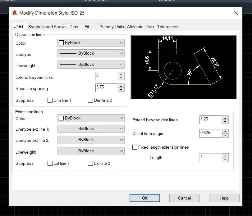
Click on the ‘Modify’ option. Another main dialogue box will open. There are different 7 tabs are available for different settings.
1. Lines
2. Symbols and Arrows
3. Text
4. Fit
5. Primary units
6. Alternate Units
7. Tolerance
1. Lines
We can change the Dimension line (Arrow lines) color, Line weight (Thickness of the line), Line Type (Continue or dashed), etc.
Also, we can edit the Extension line (Two vertical parallel lines). We can change color, line type, and line weight.
We can extend or decrease the line gap of the extension line from here.
2. Symbols and Arrows
From this tab, we can change the First arrow style and Second arrow style.
Also, we can change the arrow size as per requirement.
3. Text
From this tab, we can modify text style, text color, and fill color.
The main thing is we can change the text height from here.
Also, we can change text placement above, below, center, etc.
4. Fit
We can modify text and dimension line position from this tab.
5. Primary units
Change the unit from here, which is set at the start of the drawing in the workspace (mm, meter, cm, inch, feet, etc.)
Otherwise, it can show the wrong dimension at the time of measurement.
Also, set precision as per requirement.
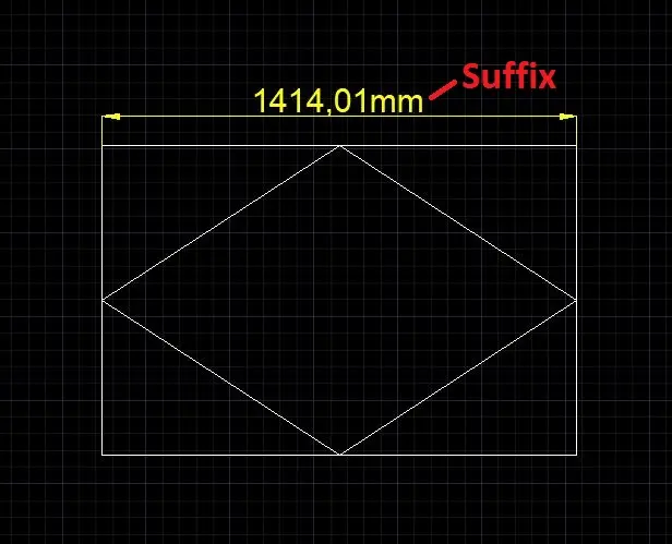
In primary units, we can show the symbol of the dimension as m, mm, inch, etc. from the ‘Prefix and Suffix’ option.
Write dimension in the prefix or the suffix as per requirement. It will show the dimensions as shown.
Also, we can change Angle units from here.
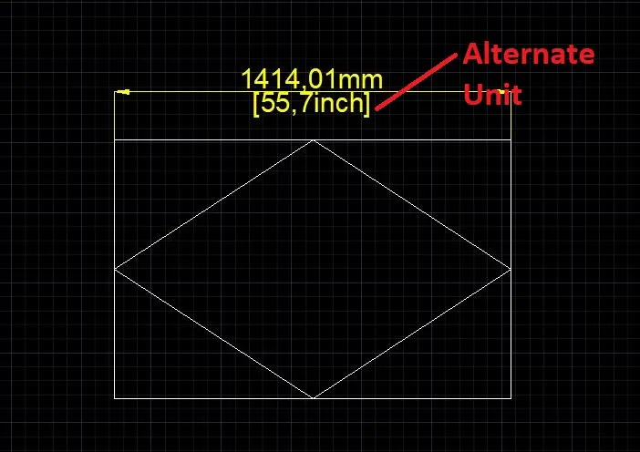
6. Alternate Units
If I want to show alternate units with the main unit, then click on ‘Display alternate units’.
It will show two units, for example, 250mm, and 0.25m.
After clicking, set alternate unit format and precision.
The main important thing is after the set unit, set ‘Multiplier for alt unit’.
It means the set relation of the multiplier or divider by the main unit.
For example, the primary unit is in mm and I want alternate units as an inch.
1 mm=0.0393701 inch. So we have to write ‘0.0393701’ as ‘Multiplier for alt unit’.
And write in the suffix, inch.
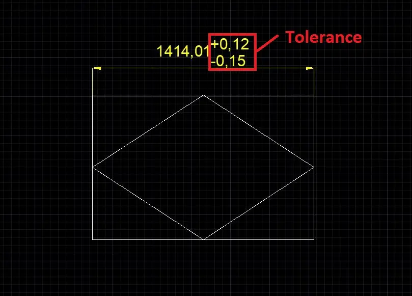
7. Tolerance
Tolerance means sometimes we have no precise dimension and we want to show some dimension is either + or – some units.
For this type of dimension, set unit, upper value, and lower value.
If there are alternate units, their tolerance also can be shown from here.
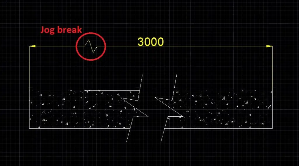
How to add a Jog (Break line) in between the AutoCAD Dimension line?
Select the ‘Annotation’ tab and select the ‘Jog line’.
Or type ‘DIMJOGL’ in the command bar and press the Enter key to invoke the command.
Then it will ask for ‘select dimension to add jog’.
Select those dimension lines in which we want to add jog.
After that, it will ask for ‘specify jog location’.
Specify the location to add the jog. Jog will be added.
Edit: (AutoCAD Dimension)
To edit jog height, select the dimension line and right-click.
Select properties from there. From that dialogue box, we can edit ‘Jog height’ and other things.
It’s done here.
Know more About AutoCAD on Youtube
Also, Read our previous Articles.
- What is AutoCAD Electrical? (99% want to Know)

- AutoCAD Student Teacher Watermark (99% A-Z Tips)
- AutoCAD Earth Ground Symbols (70% Don’t Know)..
- What Computer language was AutoCAD written in? (90% Don’t Know)
- Best 11 laptops for AutoCAD (100% You Like)

- Autodesk Takeoff 2025 | 80% of People Don’t Know (July 2025)

- AutoCAD Section Line | 100% You Don’t Know July 2025
- AutoCAD shortcut keys (80% New keys don’t Miss) July 2025
- AutoCAD 2025 software price in India (99% it’s Confusing) July 2025
- How does Autodesk clear temp files? (100% Legit Tips) July 2025


Leave a Reply