Good morning friends, In this article, you learn about How to make a thread in Solidworks, How to create a thread in Solidworks 2023 & How do you make thread screws in Solidworks. Learn about how to make internal threads in Solidworks. How to make a screw in Solidworks & How to make threads on it. So without wasting time let’s get started.
What is a thread in Solidworks?
Solidworks has an amazing feature of thread.
It permits you to both expel thread & cut the thread so this round & hollow surface can be within an opening or the external surface of a bolt shaft.
Location of Threads in Solidworks
How to make a thread in Solidworks?
The Fundamental method to make a thread in SOLIDWORKS.
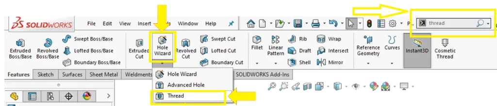
First of all, to create a thread in Solidworks we can essentially go Insert >> Features >> Thread.
After that, at that point, pick an edge of our model & go through and populate our thread particulars.
Whenever we are finished doing that, we can raise a ruckus around the town mark & there are our threads.
It truly does not get any simpler than that.
Yet, a ton of clients need to know how to make their threads in SOLIDWORKS by outlining their profile and doing a compass cut.
The Custom method to make a thread in SOLIDWORKS.
To do this we will get going with the helix we made in my last blog as we were demonstrating this hex cap screw.
Go to the top arrangement and start a sketch.
Presently, the explanation we’re utilizing the top plane is that when we made the helix.
The helix finished at zero degrees so that is precisely where our top plane is.
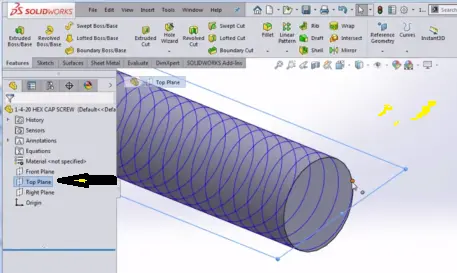
So we will start another sketch on the top plane and presently we’re prepared to portray the real thread profile.
This is where genuine wizardry happens because there are various strategies on the most proficient method to do this.
Where should the plane be found, preferably you will put the details in the Hardware’s Handbook.
Yet on the off chance that you don’t have those particulars or on the other hand on the off chance that.
You’re making a custom thread, you could have somewhat more play concerning how you make your thread.
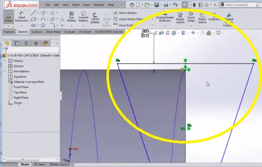
By and by, I like to make half of the thread from the outset and afterward I accept the upward line as displayed beneath and make it for development.
Then, I’ll take a window determination of the whole sketch and select the Mirror Substances order which gives me a similar thread profile on the two sides of the middle line.
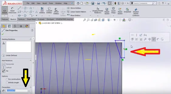
Then, I will take a point and put it sort of anywhere on the middle line and afterward put an aspect starting there to the extremely top line.
The explanation I have for that aspect is because I maintain.
There should be a smidgen of cross-over between where the thread is cutting and the extremely external most piece of the shaft by only a couple of, perhaps 0.003 inches.
Presently, I will tap on that point that I had outlined, I will hold CTRL and select the helix and I will dole out what’s known as a puncture connection.
That will snare that sketch to the helix precisely by then.
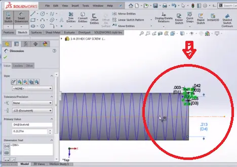
Presently I’m prepared to place in my last aspects and say I believe the separation from pinnacle should top to be .042 the pitch is .050 so that ought to give me pretty much than the ballpark.
I will make the level at the last 5 just to get myself close.
Keep Update: I know these aren’t the very perfect numbers from the Apparatus Handbook. Yet I’m simply attempting to give you something near work off of.
At long last, I will place in an aspect, perhaps I’ll take the pitching aspect.
Getting to the midpoint of that. line, drop in a middle line, drop a middle line off of the beginning.
I believe the pitch breadth should go starting here to the middle line that I made and afterward across.
Now that ought to give me something that looks very great for this cut thread, and once more, it’ll ultimately depend on you to ensure your numbers are precisely awesome.
I’m simply attempting to get in there and tell you the best way to make the sketch.
So presently I will leave that sketch and I will go to the order Features >> Cleared Slice.
And I will decide to clear that sketch that I made along the helix that I made in the past blog.
I’m seeing a see which implies I ought to be on the correct course.
Afterward, hit the green mark and there we go. We had the option to do a cut scope of those threads.
To make the lead-in for this part up at the top, I like to make a basic cut spin.
You don’t need to do this with a chamfer.
You could battle to do it with a chamfer since there’s not exactly.
A perfect edge there to chamfer off yet you can do it rapidly and effectively by making a basic triangle.
Follow this video to learn more if you don’t understand yet.
How to make internal threads in SolidWorks?
- First of all, open a part file. The measurement of the chamber is 10 millimeters. Even though you likewise make a 10-millimeter thread profile, you could make any profile on the chamber. The thread profile isn’t directed by the distance across the opening or shaft.
- Click on the import, then go to features, and go to Thread.
- Choose the top edge of the chamber, in the region of the design.
- Choose Matric type and set the Size to M10x1, in the Property Manager.
- Just click Offset, then reverse direction & now Set Offset Distance to 1 millimeter, below Thread Area.
- Now you have to click Keep up with Thread Length. This thread profile refreshes from 10-11 mm long.
- At last, click on the right tick mark.
FAQ on threads in Solidworks
Yes, you can make threads in Solidworks very easily and very accurately. Only Solidworks offers you thread tools for this kind of work.
1. Begin with a model with a roundabout component.
2. Choose the thread Instrument in the Solidworks, then select a round Edge.
3. After that, the instrument can be utilized for Solidworks Outer threads.
4. Now you have to determine the thread size & type.
5. At the end you just have to set the thread length.
Click on the hole wizard on the top bar on Solidworks. Now you can see there are three options, Wizard hole, Advanced hole, and Thread.

You can read our Other Articles
- How to Pan in Solidworks? (80% Easy 20% Hard) Mar 2025

- SOLIDWORKS 2024 System Requirements (99% Guide) March 2025

- How to Download Solidworks 2024? (100% Working) March 2025
- What is Solidworks Composer 2024? (90% Don’t know) March 2025
- What is Solidworks 2024? (99% You Don’t know Secret) March 2025
- How to uninstall Solidworks 2023? (100% Working ) March 2025
- What is Solidworks PDM 2024? (100% A-Z Guide) March 2025
- How to copy a sketch in Solidworks? (Full Secret Guide) March 2025

- What is Solidworks Speedpak? (99% People Don’t Know) March 2025
- How to make a thread in Solidworks? (85% Easy Method) March 2025


Leave a Reply